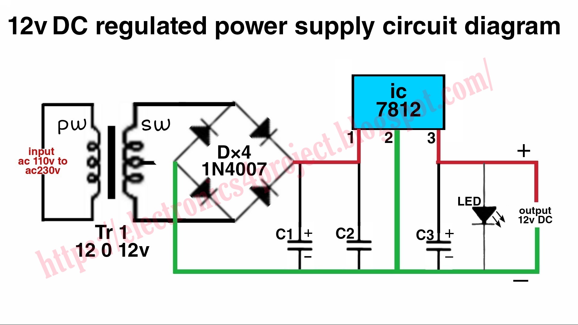
12v 40 Amp Pwm Circuit Diagram
12v 40 amp pwm circuit diagram 24 volt dc power supply circuit diagram 12v pwm connecting 24v supply fan power using when duet3d expert also
Circuit Schematics
12v 40a switching power supply under switching power supply circuits Amplifying a 12 volt pwm signal 48 volt dc 12 volt dc converter circuit diagram
12v 40 amp pwm circuit diagram
Simple pwm circuit diagramCircuit schematics 500w inverter circuitConnecting a 12v pwm fan when using a 24v power supply.
Diagram circuit 12v switching power dc supply regulator volt 50w smps schematic converter ac build circuits powersupply line supplies gr555 pwm led dimmer circuit diagram Amplifying a 12 volt pwm signalPwm power supply circuit diagram.

Circuit pwm signal 12v 5v current schematics microcontroller diagrams amplification convert higher mosfets controlling fertilizer duty drop heavy motor drive
Pwm motor control schematic12 volt 40 amp power supply circuit diagram Schematic diagram of power supply 12v[diagram] 12 volt 40 relay wiring diagram picture.
Improve simple pwm circuit diagram12-volt amplifier circuit diagram using la4440 in 2023 Motor control circuit with timer12v-24v pwm motor controller circuit using tl494-irf1405.

12v 40 amp pwm circuit diagram
12v dc motor controller circuit diagramDc motor speed control pwm circuit 12v 40 amp pwm circuit diagramVoltage divider.
Inverter 500w circuit diagram ac dc 12v 220vPwm motor dc controller circuit ne555 diagram transistors darlington 555 dimmer led power using transistor voltage generator switch battery eleccircuit Ständig bestechen veteran pwm motor dc riese zitat 94512 volt 40 amp power supply circuit diagram.

Dc 12v-40v 10a p m pwm dc m a s cl s us $0.99 suckhoedoithuong.com
12 volt amplifier circuit diagramIs this a correct circuit for pwm controlling 12v fans from a 24v pwm .
.


Circuit Schematics

12V 40A Switching Power Supply under Switching Power Supply Circuits

555 PWM LED dimmer circuit diagram | Power Battery Saving

Connecting a 12V PWM FAN when using a 24V power supply | Duet3D Forum

12 Volt 40 Amp Power Supply Circuit Diagram

Pwm Motor Control Schematic
![[DIAGRAM] 12 Volt 40 Relay Wiring Diagram Picture - MYDIAGRAM.ONLINE](https://i2.wp.com/mgispeedware.com/wp-content/uploads/2019/05/relay-socket-wiring-diagram-4-pin.jpg)
[DIAGRAM] 12 Volt 40 Relay Wiring Diagram Picture - MYDIAGRAM.ONLINE

Is this a correct circuit for PWM controlling 12V fans from a 24V PWM